-Remote control computer car
Remote control car that is connect throw a transmitter that is connected with parallel port. Wireless car in this gadget car is used that is connect with a remote
System and control the car movements.
And a computer system is used to control that remote or transmitter
That transmits the signal for car movements.
- UP key is used to FWD
- Down key is used to reverse the car.
- Right key is for turn wheel right
- Left key is for turn wheel left.
Remote control computer car
The purpose of this gadget is to control the electricity automatically
When a person is enter in the room lights turn on and it counts
The person when person going back it minuses from it’s counting.
When no person in the rooms then its value should be 0 and
Lights turn off and if person's value is greater then 0 then lights
Should be on:So first of all u will have the well know how about parallel port
· The Parallel Port?
What is the “parallel port”? In the computer world, a port is a set of signal lines that the microprocessor, or CPU, uses to exchange data with other components. Typical uses for ports are communicating with printers, modems, keyboards, and displays, or just about any component or device except system memory. Most computer ports are digital, where each signal, or bit, is 0 or 1. A parallel port transfers multiple bits at once, while a serial port transfers a bit at a time (though it may transfer in both directions at once).
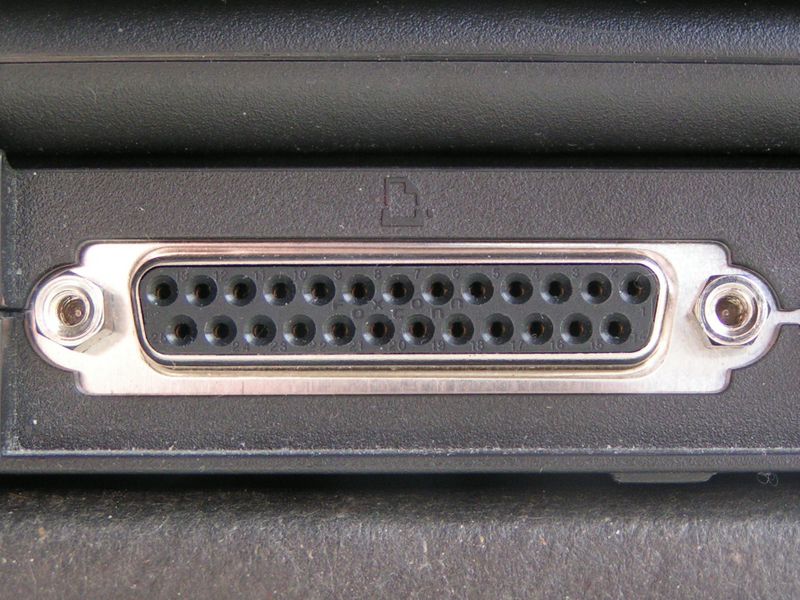
The Parallel port or line printer terminal is found commonly on the back of a PC as a D-Type 25 Pin female connector. The port is composed of 4 control lines, 5 status lines and 8 data lines.
The original parallel port is a bundle of three ports namely, data port, status port, and control port. Each of the Data, Status, and the Control port has specific addresses assigned to them. These addresses are in sequential order. That is, if the data port is at address 0x0378, the corresponding status port is at 0x0379 and the control port is at 0x037a. Thus according to the addresses displayed it follows that the address of the data port is 0x0378 and so on. Pins 2 through 9 form the 8-bit data output port. This port is purely a write-only port.
This means that it can be used only to output some data through it. Pins1, 14, 16, and 17 forms the control port which is capable of reading/writing. Pins 10 through 13 and Pin 15 together form the status port. The status port is a read-only port.
The pin outs of DB25 connector is shown in the picture below:-

The lines of DB25 connector are divided into three groups:-
1) Data Lines (Data bus)
2) Status Lines
3) Control Lines
As the name refers, data is transferred over data lines, Control lines are used to control the peripheral and the peripheral returns status signals back to the computer through Status lines.
1- Data Register
The Data port, or Data register, (D0-D7) holds the byte written to the Data outputs. In bidirectional Data ports, when the port is configured as input, the Data register holds the byte read at the connector’s Data pins. Although the IEEE-1284 standard refers to the Data lines as D1 through D8, in this project, I use D0-D7 throughout, to correspond to the register bits.
Data register (Base Address) | ||
Bit | Pin: D-sub | Signal Name |
0 | 2 | Data bit 0 |
1 | 3 | Data bit 1 |
2 | 4 | Data bit 2 |
3 | 5 | Data bit 3 |
4 | 6 | Data bit 4 |
5 | 7 | Data bit 5 |
6 | 8 | Data bit 6 |
7 | 9 | Data bit 7 |
2- Status Register
The Status port, or Status register, holds the logic states of five inputs, S3 through S7. Bits S0–S2 doesn’t appear at the connector. The Status register is read-only, except for S0, which is a timeout flag on ports that support EPP transfers, and can be cleared by software. On many ports, the Status inputs have pull-up resistors. In their conventional uses, the Status bits have the following functions:
S0: Timeout. In EPP (Enhanced Parallel Port) mode, this bit may go high to indicate a timeout of an EPP data transfer. Otherwise unused. This bit doesn’t appear on the connector.
S1: Unused.
S2: Unused, except for a few ports where this bit indicates parallel port interrupt status (PIRQ). 0 = parallel-port interrupt has occurred; 1 = no interrupt has occurred. On these ports, reading the Status register sets PIRQ = 1.
S3: nError or nFault. Low when the printer detects an error or fault. (Don’t confuse this one with PError (S5). below.)
S4: Select. High when the printer is on-line (when the printer’s Data inputs are enabled).
S5: PaperEnd, PaperEmpty, or PError. High when the printer is out of paper.
S6: nAck or nAcknowledge. Pulses low when the printer receives a byte. When interrupts are enabled, a transition (usually the rising edge) on this pin triggers an interrupt.
S7: Busy. Low when the printer isn’t able to accept new data. Inverted at the connector.
Status register (Base Address + 1) | ||
Bit | Pin: Dsub | Signal Name |
3 | 15 | nError (nFault) |
4 | 13 | Select |
5 | 12 | PaperEnd |
6 | 10 | nAck |
7 | 11 | Busy |
3- Control Register
The Control port, or Control register, holds the states of four bits, C0 through C3. Conventionally, the bits are used as outputs. On most SPPs, however, the Control bits are open-collector or open-drain type, which means that they may also function as inputs. To read an external logic signal at a Control bit, Bits C4 through C7 don’t appear at the connector. In conventional use, the Control bits have the following functions:
C0: nStrobe. The rising edge of this low-going pulse signals the printer to read D0-D7. Inverted at the connector. After boot up, normally high at the connector.
C1: AutoLF or Automatic line feed. A low tells the printer to automatically generate a line feed (ASCII code 0Ah) after each Carriage Return (ASCII 0Dh).
Inverted at the connector. After bootup, normally high at the connector.
C2: nInit or initialize. Pulses low to reset the printer and clear its buffer. Minimum pulse width: 50 microseconds. After bootup, normally high at the connector.
C3: nSelectIn. High to tell the printer to enable its Data inputs.
C4: Enable interrupt requests. High to allow interrupt requests to pass from nAck (S6) to the computer’s interrupt-control circuits.
C5: Direction control. In bidirectional ports, sets the direction of the Data port Set to 0 for output (Data outputs enabled), 1 for input (Data outputs disabled) Usually you must first configure the port for bidirectional use (PS/2 mode) in order for this bit to have an effect.
C6: Unused.
C7: Unused, except for a few ports where this bit performs the direction-setting function normally done by C5.
Control register (Base Address + 2) | ||
Bit | Pin: Dsub | Signal Name |
0 | 1 | nStrobe |
1 | 14 | nAutoLF |
2 | 16 | nInit |
3 | 17 | nSelectIn |
Hardware used...
1) Remot control Car
2) Parallel port
3) Transistor and Resistor.
1) Remot control Car
Buy a remote control car then open the remote of the car or giving the signal to the remote from parallel port
 |
| backside of remote |
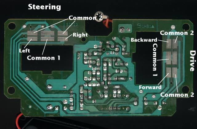
now open the remote as shown in pictue.
 | |
| Open remote |
next step is

next step is.
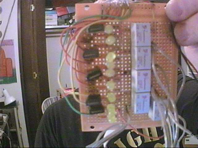
 |
| connection for parallel port. |
2) Parallel port
see above
3) Transistor and Resistor.

tanistor we can use for switching as shown in fig.
digital output camming from printer port and these transistor can control the channel of car.
and combine transistor togather for operate Remote.
Now our hardware is ready to use...
Software.
i used C# to control the lpt port. inpout32.dll is used to access the lpt port
ther is two function of this dll
Input(address);
Output(address,value);
you need to dot net 2.0 (22.5mb)
Coding......

private void car_control_KeyUp(object sender, KeyEventArgs e)
{
if (e.KeyCode == Keys.Up) { output -= 1; up = false; }
if (e.KeyCode == Keys.Down) { output -= 2; down = false; }
if (e.KeyCode == Keys.Left) { output -= 8; lleft = false; }
if (e.KeyCode == Keys.Right) { output -= 4; right = false; }
portacess.Output(address, output);
}
private void car_control_KeyDown(object sender, KeyEventArgs e)
{
if (e.KeyCode == Keys.Up & up != true)
{
output += 1; up = true;
}
if (e.KeyCode == Keys.Down & down != true)
{
output += 2; down = true;
}
if (e.KeyCode == Keys.Left & lleft != true)
{
output += 8; lleft = true;
}
if (e.KeyCode == Keys.Right & right != true)
{
output += 4; right = true;
}
hi..can you make a rc car control by wifi with ip cam using arduino with wifi shield and the program use is vb.net.
ReplyDeletecheap item as possible..
This comment has been removed by a blog administrator.
ReplyDelete